 |
| October 14, 2014 | Volume 10 Issue 38 |
Designfax weekly eMagazine

Archives
Partners
Manufacturing Center
Product Spotlight
Modern Applications News
Metalworking Ideas For
Today's Job Shops
Tooling and Production
Strategies for large
metalworking plants
Engineer's Toolbox:
Protecting motor bearings from electrical damage
By Karyn Caverly, Applications Engineer, KLOZURE Division
Garlock Sealing Technologies
Bearing isolators, like contact lip seals, are used to retain lubrication, exclude contamination, and extend the service life of the equipment in which they are installed. Figure 1 depicts a typical lip seal configuration used to prevent lubrication egress and contamination ingress. Both functions, which would normally require at least two oil seals, can be performed by a single bearing isolator.
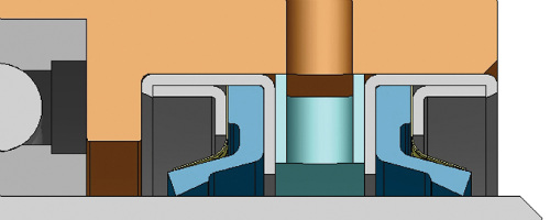
Figure 1.
Historically, bearing isolators have consisted of metallic components with simple pathways acting as dynamic sealing elements and O-rings providing static seals on the shaft and bore housing. Today's bearing isolators are highly engineered with tight tolerances, intricate labyrinth pathways with abrupt directional changes, and special features for improved sealing (Figure 2).
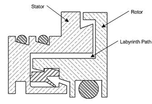
Figure 2.
Standard bearing isolators are used to prevent premature bearing failure due to condensation from daily washdowns, inadequate labyrinth excluder ring (LER) seals, and aggressive chemical attack. They are available in a variety of designs and materials depending upon the application requirements, which include size, temperature, application parameters (i.e. misalignment), media, pressure, and speed, also referred to as "STAMPS." This information will determine the type of material to be used, as well as any special features needed to adequately seal the application. If the sealing solution is based on inaccurate or incomplete information, it may result in problems later on.
Industry standards
The American Petroleum Institute's API 610 standard requires that all bearing isolators for the petroleum, heavy-duty chemical, and gas industries be made of non-sparking material. Although this standard applies strictly to these industries, it has been adopted by others as well. As a result, bronze is the most common material used in the manufacture of metallic bearing isolators. Stainless steel also can be used, even though it does not comply with the standard.
If a metallic bearing isolator is not mandatory, polytetrafluoroethylene (PTFE) mixtures can be used, either for cost savings or to provide an isolator that is more chemical resistant or suitable for FDA applications. O-ring material should also be considered in evaluating the application. Most manufacturers equip their standard bearing isolators with brown fluoroelastomer (FKM) O-rings. Depending on the application, O-rings made of PTFE-encapsulated FKM, AFLAS, or silicone should be specified instead. Improper material selection may cause O-rings to be the first component to fail in the event of chemical attacks or extreme temperatures.
Size and temperature are often assumed to be sufficient information for a manufacturer to provide an effective sealing solution. Although both are important, all the STAMPS data is needed to provide a viable bearing isolator for a particular application. Application data sheets help ensure all relevant information is collected, and should be completed for review by application and product design engineers.
Special features
Special features for bearing isolators are a relatively new development in response to user demand. For most applications, either an oil seal or bearing isolator can be used. Conventional wisdom has it that contact lip seals prevent either oil leaks or contamination ingress. However, bearing isolators will perform the same functions and last five to seven times as long. In addition, they can now provide electrical protection for equipment as well.
Electric induction motors with pulse-width-modulated (PWM) variable frequency drives (VFD) allow torque and horsepower to be precisely controlled to optimize both process parameters and energy requirements. Instead of running motors continuously at full speed and load, they can be adjusted to the exact values needed. This control provides instant power savings, enabling motors designed to run at 100 rpm to run at 60 rpm to reduce electric draw.
A newly developed shaft-grounding isolator prevents damage to motor bearings controlled by VFDs. Combining proprietary bearing isolator technology and shaft grounding rings, it retains lubrication, excludes contamination, and dissipates stray voltages that accumulate on the shaft (Figure 3).
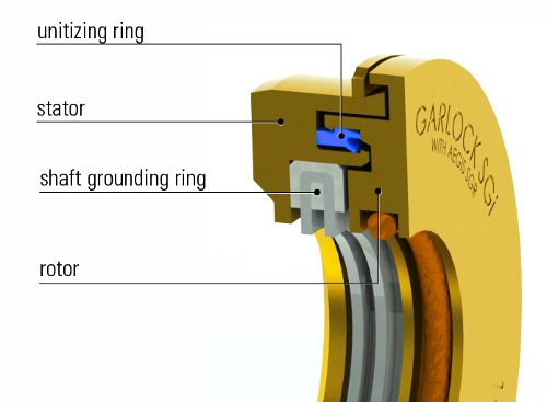
Figure 3.
Variable frequency drives
Uncontrolled electric induction motors are designed for operation with three-phase sine-wave power, either 50 or 60 Hz. The frequency, phase, and amplitude of input power are balanced, and the sum of the three phases always equals zero volts, referred to as common-mode voltage (Figure 4).
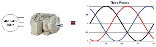
Figure 4.
However, when a motor is operated by a VFD, power is supplied in a series of pulses instead of a smooth sine wave. The input power is never balanced because the voltage is either zero, positive, or negative with rapid switching between pulses. The three phases of voltage pulses ensure that the common-mode voltage is never equal to zero, a dynamic referred to as a square wave, or six-step voltage (Figure 5).
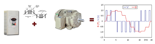
Figure 5.
As this voltage is transferred to the motor, the pulses create a capacitive coupled common-mode voltage on the shaft. The voltage seeks the path of least resistance to ground, which in most cases is through the bearings. The voltage builds up until it exceeds the insulation level of the bearings' oil film, then arcs through the bearings, creating an electrical discharge machining (EDM) pit from the rapid melting and cooling of the steel surface. Thousands of such pits can be created in a matter of seconds, and over time the ball rolling over this surface will cause what is known as fluting damage (Figure 6). As the bearing elements roll over these fluted races, the motor emits a high-pitched whine.
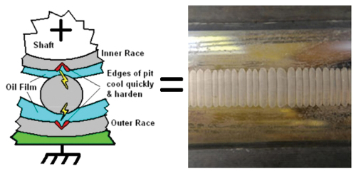
Figure 6.
A number of solutions have been developed to address this problem, including the use of ceramic or insulated bearings, installation of carbon or copper brushes to maintain contact with the shaft, and the use of conductive grease. Ceramic bearings prevent the discharge of shaft current, but the technology is costly. Motors with ceramic bearings must be specially ordered and often have long lead times, and coated bearings can be easily damaged during installation.
Carbon or copper brushes can be practical and economical ways to provide a path to ground, but they wear quickly and collect contaminants on their bristles, which reduce their effectiveness. They also require regular maintenance, which effectively increases costs.
Conductive grease contains particles that provide a lower impedance path, so shaft current can bleed off through bearings without damaging them. However, the conductive particles increase mechanical wear on bearings and often cause costly premature failures.
Recently, some manufacturers have added conductive brushes to traditional bearing isolators to prevent stray voltage from passing through the bearings. These brushes act as the path of least resistance for the voltage to travel to ground without fluting the bearings. They dissipate any existing common-mode voltage from the shaft and prevent future EDM from occurring. It is important to note that once a bearing has been fluted, a shaft-grounding bearing isolator cannot reverse the damage.
Combining non-sparking, non-contact labyrinth seal technology with a voltage grounding ring, the easily installed, maintenance-free shaft-grounding isolator eliminates damage to motor bearings. The shaft grounding ring maintains continuous contact with the shaft despite any runout, and since it is not spring-loaded, causes only negligible wear of the microfibers.
Applications
Although it is designed for use primarily with VFD-controlled motors, the new isolator can be used in any motor application. For motors up to 100 hp, it is installed on either the drive or non-drive end in combination with a standard bearing isolator on the opposite end (Figure 7). For larger, higher-power motors (above 100 hp), most manufacturers also recommend installing insulated bearings on the non-drive end to ensure all stray voltage is forced through the conductive brushes and delivered safely to ground.
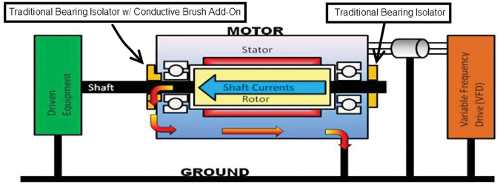
Figure 7.
Its performance meets NEMA MG 1-2003 per IEEE 841-2001, and the standard version is rated to IP56. Fitted with a standard FKM fluoroelastomer rotor O-ring, it can also be supplied with alternative O-ring materials.
The isolator can accommodate axial motion from 0 to 0.025 in. (0 to 0.6 mm), and shaft diameters from 0.875 to 6.00 in. (22.2 to 152.4 mm). Misalignment and runout (in. @ fpm; mm @ m/s) are 0 to 0.020 in. (0.5 mm). Pressure rating is ambient and temperature range is -22 F to +300 F (-30 C to +149 C). Designed to replace both contact lip seals and traditional bearing isolators, it is available in flanged, flangeless, and custom configurations.
Want more information? For general info, go to www.garlock.com/en/.
To learn about Garlock bearing isolators, go to www.garlock.com/en/product/bearing-isolators.
Published October 2014
Rate this article
View our terms of use and privacy policy